
I’m currently involved in a project to set up a solar powered wireless station and wanted to remotely monitor the battery charge process. I looked into a number of charge controllers to see if any of them could be connected to a computer. Many of the controllers have ethernet and built in web servers, but these come at a cost.
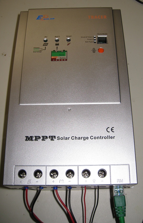
The (relatively) cheap chinese made EP Solar Tracer MPPT Solar charge controllers have an RJ45 interface for an MT5 remote display which means that there must be some way to get data out of the charge controller.
A couple of google searches for things like:
Brought up all sorts of documentation, much of the protocol information conflicted, but it all seemed to infer that the interface was serial of some sort.
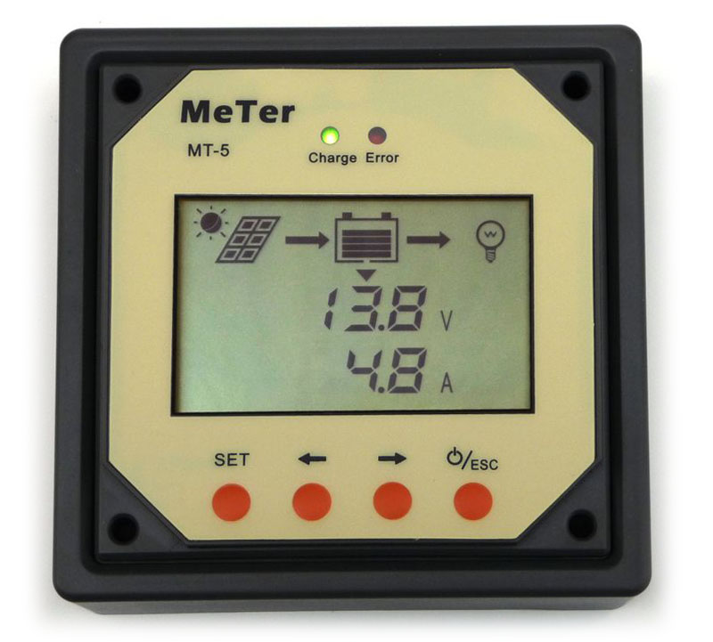
I purchased the 40 Amp Tracer and borrowed a MT5 remote display and started snooping on the interface with a multimeter, oscilloscope and logic analyzer.
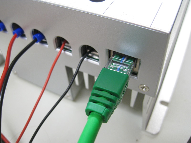
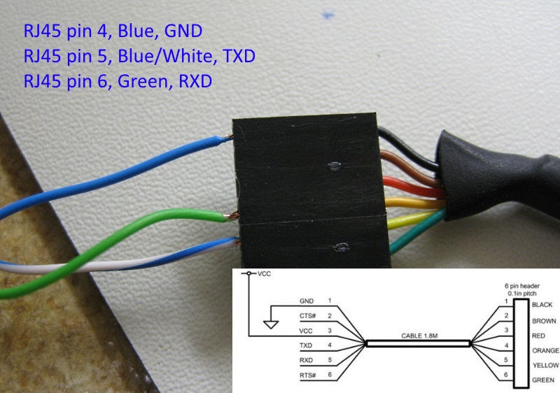
I was able to quickly verify the physical interface pin out.
Here’s the pin out of the RJ45 interface.
| Pin1 | +12V |
| Pin2 | N.C |
| Pin3 | +12V |
| Pin4 | GND |
| Pin5 | TXD |
| Pin6 | RXD |
| Pin7 | GND |
| Pin8 | GND |
WARNING: Pins 1 and 3 of the interface supply 12 volts DC. I’m unsure if these are fused, so be very careful not to short them to ground. Note that pin 4 is a ground, so it would be relatively easy to short pins 3 and 4 together.
The pin order is defined as: plug-oriented touch-sided view of the direction of the cable down, from left to right order of 1 to 8…. Or at least that’s how one of the translated Chinese documents describes the pin order.
Here’s a picture (courtesy of wikipedia) for clarication.
The serial interface runs at 9600/8-N-1 (9600 baud, 8 data bits, No parity bit and 1 stop bit) on 3.3 Volt TTL Logic.
A FTDI TTL-232R-3V3 USB to TTL serial adapter works well for testing purposes.
I want to interface the charge controller to a Raspberry Pi which is convenient as the RPi UART also works on 3.3Volt TTL logic levels.
I haven’t fully worked out the protocol yet.
The MT5 continually sends the packet
0xAA 0x55 0xAA 0x55 0xAA 0x55 0xEB 0x90 0xEB 0x90 0xEB 0x90 0x16 0xA0 0x00 0xB1 0xA7 0x7F |
which loosely matches some of the documentation I’ve found online.
It looks like the response is a number of 16 bit integers (Least significant byte first) and 8 bit bool values. I’m still working on this and hope to have a result soon.
